💡 TL;DR: “Multi-cluster” is not one problem. It is a bundle of loosely related problems (placement, lifecycle, networking, traffic, policy, identity, observability, data) that pull in different directions. That is why there is no single standard or winner, and why the best setups compose focused tools per dimension instead of chasing one platform to rule them all.
Kubernetes won because it gave the industry a strong single-cluster abstraction. You describe workloads, services, config, and desired state, and the control plane continuously works toward that state inside one cluster.
Multi-cluster never got the same clean abstraction. Not because people have not tried, and not because the tooling is immature in some simple linear way. The more uncomfortable answer is that “multi-cluster” is not one problem. It is a label we put on many different problems that happen to involve more than one cluster.
That distinction matters. If two teams say they need multi-cluster, they may mean completely different things. One team wants safer cluster upgrades. Another wants to deploy the same app to every region. Another wants failover during regional outages. Another wants service-to-service traffic across clusters. Another wants policy enforcement across a fleet. Another wants a global scheduler. Another wants disaster recovery for stateful systems.
Those are related, but they are not the same problem.
🧩 Multi-cluster is many dimensions, not one dimension
When people talk about multi-cluster, they usually mean some combination of these dimensions:
- Fleet inventory and cluster lifecycle: create, upgrade, patch, rotate, scale, and delete clusters.
- Workload and config distribution: roll out apps, manifests, policies, and platform components across many clusters.
- Workload placement: decide which cluster should run a workload based on capacity, cost, latency, compliance, availability, or business intent.
- Networking and service discovery: allow services in one cluster to find and call services in another cluster.
- Traffic management: route users to the right region or fail over when a cluster or region is unhealthy.
- Policy, identity, and security: enforce consistent rules without flattening trust boundaries.
- Observability: understand a fleet as one system while still preserving per-cluster ownership and debugging context.
- Stateful data and disaster recovery: keep data available, replicated, recoverable, and consistent enough for the application.
The problem is that each dimension has different owners, different failure modes, and different definitions of success.
Cluster lifecycle is usually a platform engineering problem. Workload rollout may belong to app teams or platform teams depending on the organization. Global traffic often belongs to networking, edge, or SRE teams. Identity and policy involve security teams. Stateful failover is usually an application and data-platform problem before it is a Kubernetes problem.
Trying to solve all of that with one “multi-cluster platform” is where the abstraction starts to crack.
🧱 The cluster boundary is not an accident
A Kubernetes cluster is not just a scheduling bucket. It is also a failure boundary, trust boundary, quota boundary, upgrade boundary, API boundary, and often an ownership boundary.
That is why multi-cluster exists in the first place. Organizations use multiple clusters to reduce blast radius, isolate tenants, separate environments, place workloads near users, satisfy data residency rules, or avoid coupling every workload to one giant control plane.
But many multi-cluster systems are tempted to make many clusters look like one big cluster. That sounds attractive until you look closely.
If many clusters behave like one cluster, what happens during a network partition? What if one cluster is two Kubernetes versions behind? What if a policy is valid in one region but illegal in another? What if capacity exists in a cluster, but the data needed by the workload does not? What if traffic fails over cleanly but the downstream dependency does not? What if the global control plane is healthy, but one member cluster is slowly failing?
These are not edge cases. They are the normal operating conditions of distributed systems.
This is the core reason there is no obvious winner. A universal abstraction has to hide complexity, but multi-cluster correctness often requires exposing complexity. The operator needs to know which cluster is broken, which boundary is being crossed, which policy applies, which data is stale, and which failure mode is acceptable.
🧰 The status quo is a toolbox, not a single platform
In practice, successful multi-cluster setups tend to be composed from narrower tools.
GitOps is commonly used for workload and configuration distribution. It is not a complete multi-cluster solution, but it is a good answer for “make these desired states show up consistently across these clusters.”
Cluster lifecycle tools, including cloud provider fleet managers and Cluster API-style approaches, focus on creating, upgrading, and operating clusters. They solve a platform operations problem, not global application scheduling.
Gateway, ingress, DNS, CDN, and global load-balancing systems often handle user-facing traffic. They are usually the right layer for north-south failover and traffic steering because the user enters the system from outside the cluster anyway.
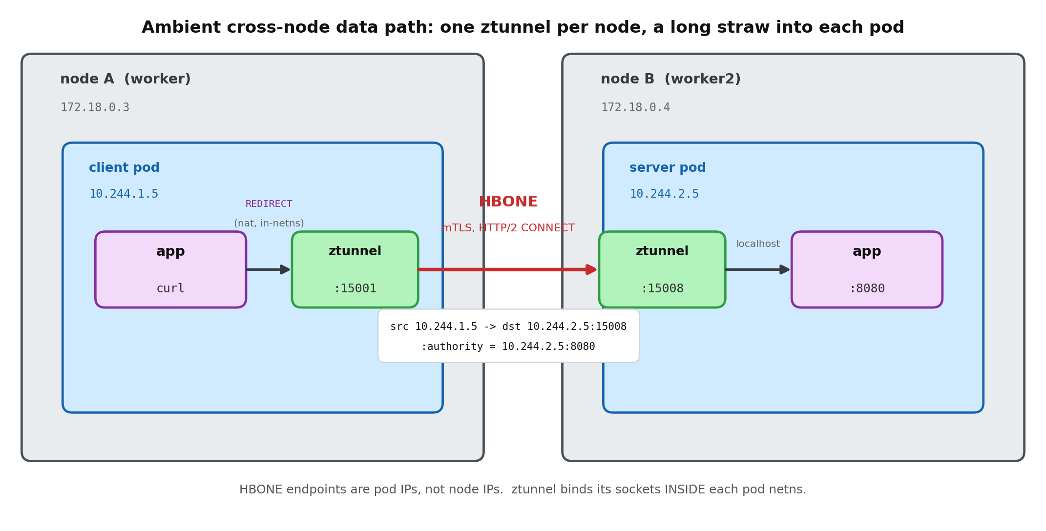
A service mesh is usually the stronger answer for cross-cluster service-to-service traffic. It gives you workload identity, mutual TLS, service discovery, and traffic policy as a consistent layer instead of a pile of per-app glue. The historical objection was cost: the sidecar-per-pod model added latency, memory, and upgrade pain that made many teams shy away. Ambient mode changes that calculus. By moving mTLS and L4 identity into a shared per-node layer and making the L7 proxy optional and only-when-needed, it removes the sidecar tax and makes a secure cross-cluster mesh far cheaper to run at scale. That is what turns “mesh across clusters” from a heavy commitment into a reasonable default.
Kubernetes-native Multi-Cluster Services exists in the same space, but it is a narrower primitive. It handles scoped service discovery and can stitch a service across clusters, yet it stops short of identity, encryption, and traffic policy, so you usually end up bolting a mesh on top anyway. In practice it is a supporting detail, not the foundation you build cross-cluster connectivity on.
Policy engines help enforce governance across fleets. Observability systems centralize metrics, logs, traces, and events so teams can see fleet-wide patterns without pretending every cluster is the same.
None of these categories is fake. They are all useful. But each solves a slice. Calling any one of them “the multi-cluster solution” is usually marketing shorthand.
⚠️ Where current approaches still fall short
The weakest area is probably workload placement. People want to say, “run this workload in the best cluster,” but “best” depends on real-time capacity, cost, latency, compliance, affinity, data location, failure domains, upgrade windows, and business priority. That is a lot of intent to encode, and most organizations do not have clean enough signals to automate it safely.
Cross-cluster networking is another trap. It is easy to draw a diagram where services talk across clusters. It is much harder to operate that path during certificate rotation, DNS drift, asymmetric latency, packet loss, policy mismatch, partial outage, and incident response. Every cross-cluster dependency can turn a local failure into a distributed failure.
Stateful workloads remain the hardest part. Kubernetes can restart pods. It cannot magically decide your data consistency model. Multi-region databases, replication lag, backup restore, failover ordering, and application-level reconciliation usually matter more than the Kubernetes object that launched the pod.
Ownership is also unresolved. Platform teams want standardized control. App teams want autonomy. Security teams want enforceable policy. SRE teams want debuggability. A multi-cluster system that hides too much makes incidents harder. A system that exposes everything becomes too complicated for most teams to use.
That tension is not going away.
🏗️ The future is layered, not monolithic
The future of Kubernetes multi-cluster is probably not one grand control plane that makes every cluster disappear behind a single API. It is a set of layered standards with honest interfaces between them, where each layer owns one dimension, preserves the cluster boundary, and exposes a clear contract to the next.
A workable model looks like this:
- Use fleet tooling for cluster lifecycle: create, upgrade, patch, rotate, and retire clusters.
- Use GitOps or desired-state distribution for apps and platform config.
- Use Gateway, DNS, CDN, or global load balancing for user-facing traffic.
- Use a service mesh for explicit east-west service calls, identity, and mTLS, and prefer ambient mode so the security layer does not cost you a sidecar per pod.
- Use policy and identity systems to enforce rules consistently without flattening trust.
- Use centralized observability to see the fleet while preserving per-cluster debugging context.
- Treat stateful failover as a data-platform and application problem, not a scheduler problem.
Several of these layers are already maturing. Gateway API is standardizing more of the traffic story, service mesh is becoming the default way to carry identity and encrypted service-to-service traffic across clusters (ambient mode in particular is removing the sidecar overhead that used to make people hesitate), and GitOps has become the default distribution mechanism because it fits the shape of the problem: versioned desired state applied independently to many targets. None of them tries to be the whole answer, and that is exactly why they work.
The point is not one API that hides every cluster. It is the contracts between layers: how workloads are distributed, how traffic moves, how identity is trusted, how policy is enforced, how failures are isolated, and who owns each decision.
Automation and AI may help here, especially for operations: summarizing fleet health, detecting unsafe rollout patterns, recommending placement, or correlating incidents across clusters. But automation only helps when intent and safety boundaries are explicit. If the system does not know whether latency, cost, compliance, or availability matters most, it cannot make a good placement decision. It can only make a confident-looking guess.
🧭 The practical advice
So stop treating multi-cluster as one product category, and start by naming the dimension you are actually solving. Consistent deployment, safer upgrades, regional failover, cross-cluster service calls, and disaster recovery are different problems with different owners, and the layered model above already tells you where each one lives. Pick the tool for that layer instead of shopping for a platform that claims all of them.
Multi-cluster is real. The need is real. But the phrase is too broad to produce one clean winner. The winning approach is not to make many clusters pretend to be one cluster. It is to manage many clusters while being honest about why they are separate, which boundaries should stay intact, and which cross-cluster problems actually need to be solved.


